-

hartownia
hartownia
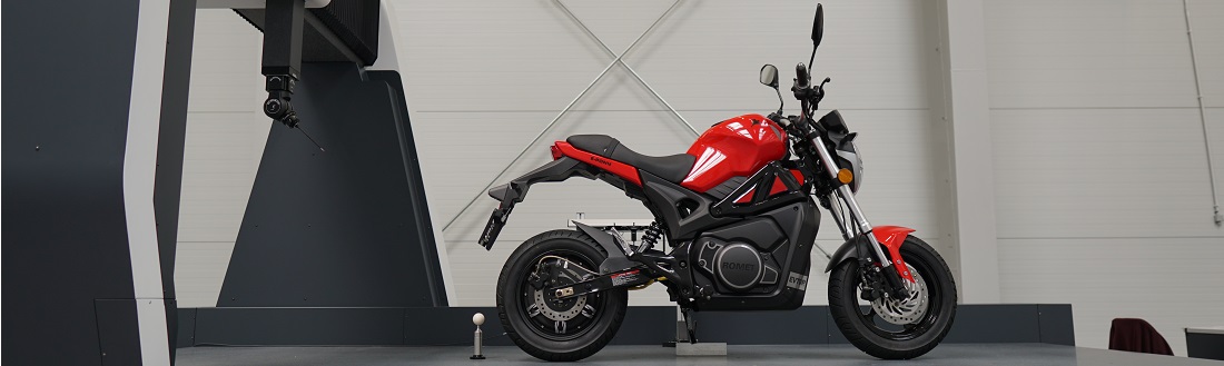
GG Tech is working on the development of the so-called continuous cutting technology on milling machines. In the current state of development of this technology, it can be applied to appropriate machine tools for a wide spectrum of surface types. The method has a great potential in surface finishing and many non-technological elements in the milling process. We are looking for partners for the development of this surface treatment method, mainly in terms of programming support in CAM systems and the design of the machine tools themselves.
Performance
The continuous cutting method had proven to be very efficient in keeping the cutting speed at least at a minimum level of Vc. By the nature of the method, this speed is equal to the feed. Therefore, it requires the use of machine tools with high operating speeds of controlled axes (over several thousand mm / min). Making a sample using the continuous cutting method takes 60% less time than the classic method, while maintaining better roughness parameters. It should be noted that this time may be several times faster when confronting the samples with the classical method of similar Ra, because at maximum spindle revolutions the only way to improve the roughness is to reduce the feed, which extends the process. The surfaces made for the purpose of the study were relatively small (about 100mm long). Due to the dynamics of the machine tool, machining times will be significantly reduced when making longer surfaces and the time will be longer for shorter ones.
Surface quality
The continuous cutting method, compared to the classic method, gives much better roughness values along the cutting line and comparable values perpendicular to the cutting direction. However, it should be noted, that the sample made with the classical method was milled with a tool with almost twice the radius. Accuracies are on a very comparable level with the advantage for the classical method (differences on the order of 1-2 micrometers). The accuracy of the continuous cut method deteriorates as the machining area is moved away from the rotary axes. This is due to the action of the distance from the tool contact point to the rotary axis as the angular position, velocity, and acceleration error multiplier. It manifests itself mainly by deterioration of the surface waviness. Speed and acceleration errors are greatest and can be minimized on a specific machine by using lower feed rates. They could also be reduced by using better drives and axis measuring systems, but this is a task for machine tool builders and goes beyond the capabilities of technologists and programmers. Errors resulting from the position of the angular axes cannot be minimized by the technologist and programmer because they result from the construction of the machine tool. However, when comparing the continuous cutting machining with the classical machining in a smooth four / five axis, the 2 micron shape deterioration encountered will be the same.
The use of the continuous cutting method on milling machines with a swivel-rotary head instead of the cradle, or a rotary table plus a tilting head, will give greater opportunities to control shape errors due to the constant distance of the rotary axes from the tool edge. This configuration of the machine tool kinematics guarantees constant values of the obtained shape tolerances on any large work piece (throughout the entire machining range of a given machine tool).


Practical Applications
The continuous cutting method is used mainly in finishing (milling from 2.5 to 6 axes) of surfaces that allow the introduction of a path for acceleration and deceleration of the tool, or if the surface parameters on a given specific part will allow start and end of cutting from 0 mm/min .Thus, open surfaces (not limited by vertical walls) can be processed without major problems. Surfaces with vertical walls can be processed using a special path trajectory strategy or special tools. The current possibilities of CNC programming with the use of computer assist systems (CAM) are very large. However, they could be successfully developed mainly for the use of standard turning tools, boring bars or special tools in milling machining strategies and the generation of these strategies, tool inputs and outputs in the aspect of maintaining a minimum cutting speed Vc. Current CAM systems in milling strategies do not support at all the smooth use of the sixth axis in the machine spindle and such support would be crucial due to the above-described problems.
The method can be used in shaping low-tech internal corners due to the possible use of blades with minimal radii of high stiffness (e.g. 0.05 mm or less).
It is possible to use any turning and milling inserts, which gives great opportunities to match the appropriate tool to the surface being processed. The use of ready-made handles and holders as well as the construction of self-made tools extends the spectrum of possible shapes.
Durability
Machine tool – the main factor affecting the durability of the spindle is its zero rotation speed during machining. The spindle rotates only in positioning or at very low speed when machining with a smooth sixth axis. The disadvantage of the method due to the durability of the machine is its dynamic operation, which, however, results in a shorter processing time of a given part.
Tools – today’s machine tools are characterized by the possibility of obtaining very high feed rates (several dozen thousands of mm/min).